






GUNDAM ROBOTICS SYSTEMS // INDUSTRIAL PRODUCTION MANUAL
Primary Production Facility: Southport Works — Renton, Washington
Design Paradigm: Kinetic Energy Harvesting / Solid-State Damping Array
Host Framework Execution: AlmaLinux 9.x Distributed Secure Node Clusters
Logic Standard: Native 16-State 0.0V–1.0V Voltage-Level Logic [0.0625V Increments]
Design Paradigm: Kinetic Energy Harvesting / Solid-State Damping Array
Host Framework Execution: AlmaLinux 9.x Distributed Secure Node Clusters
Logic Standard: Native 16-State 0.0V–1.0V Voltage-Level Logic [0.0625V Increments]
1. ARCHITECTURAL OVERVIEW: THE KINETIC RECOVERY INITIATIVE
The Kickstart Regenerative Shock Absorber (K-RSA) system is an energy-harvesting structural component designed to replace passive hydraulic fluid dampers and mechanical spring assemblies. Standard shock absorbers dissipate severe impact forces and high-vibration energy as wasted heat. The K-RSA system converts this lost kinetic energy directly into regulated, high-density electrical energy.
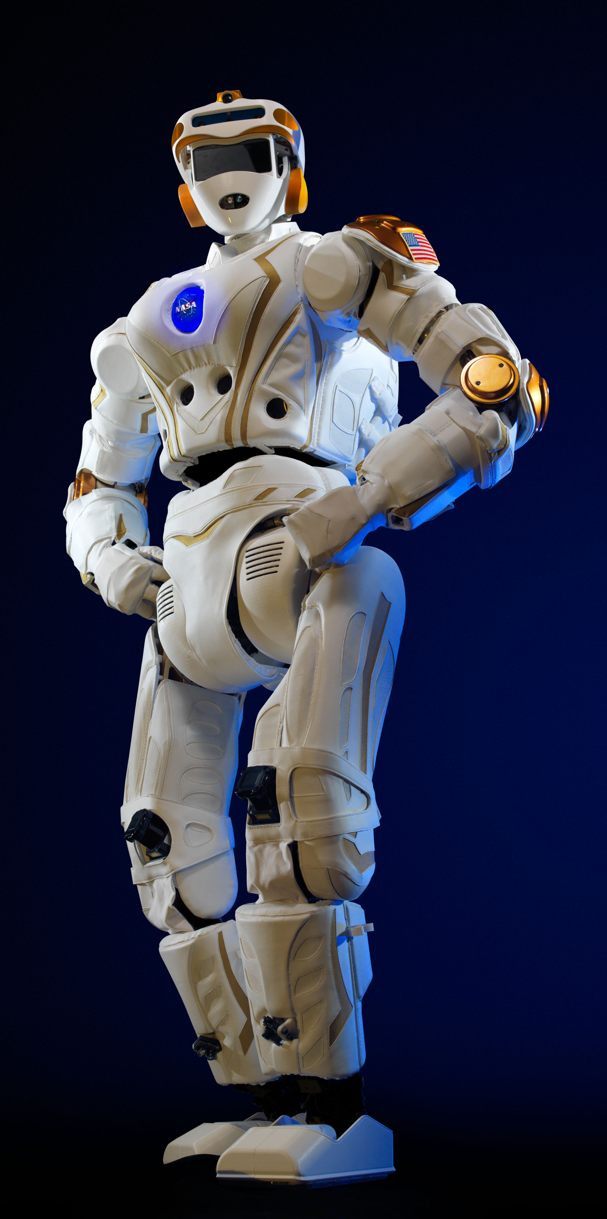
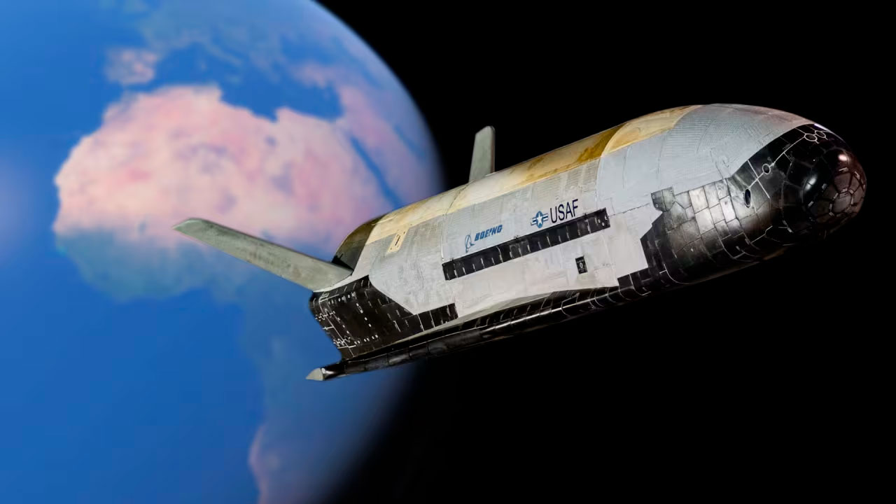
This system provides continuous passive power generation during high-impact mobile suit movements, tracked vehicle transit, or space capsule recovery landings.
2. CORE ELECTROMECHANICAL PHYSICS & HARVESTING LOGIC
The high-speed power conversion and dynamic damping profiles are executed via a custom VHDL feedback sequence on dedicated FPGAs, monitored in real time by Numba-accelerated parallel loops (
@njit parallel=True) running across host CPU execution threads simultaneously.A. The Linear Energy Induction Sequence
To capture incoming kinetic shock vectors without mechanical gears, the actuator controller monitors a Linear Electromagnetic Generator (LEG) embedded directly inside the main piston shaft:
$$P_{\text{harvested}} = \eta \cdot \int_{0}^{t} \left( F_{\text{impact}}(t) \cdot \mathbf{v}_{\text{piston}}(t) \right) dt \quad \text{and} \quad V_{\text{induced}} = -N \cdot \frac{d\Phi_B}{dt}$$
Where:
- $F_{\text{impact}}(t)$ is the external compression force acting on the damper assembly.
- $\mathbf{v}_{\text{piston}}(t)$ is the instantaneous linear velocity of the shock piston.
- η represents the mechanical-to-electrical energy conversion transformation efficiency.
- N is the turn density of the internal copper wire windings.
- $\frac{d\Phi_B}{dt}$ is the rate of change of the magnetic flux through the internal coil sections.
When a heavy vehicle undergoes sudden, high-G mechanical impacts, the linear movement drives permanent neodymium magnets through the internal coil array. This movement induces a high-voltage back-EMF, providing immediate electrical generation while generating passive electromechanical damping to stop structural bottoming-out.
B. The 16-State Dynamic Stiffness Matrix
The system uses 16-state logic mapping across all internal induction coils. By adjusting the load impedance across the coils in precise 0.0625V intervals, the flight computer can instantly modify the mechanical resistance of the shock. This method enables real-time adjustments to create a soft dampening profile for smooth transit or a rigid setting for high-impact landings without valve latency.
3. HARDWARE SPECIFICATION & POWER ARCHITECTURE
- The Grid-Injected Charger Bus: Captured power passes through a rectifying power management module, feeding directly back into local Snap-Circuit High-Voltage Power Lines.
- Physical Protection & Shock Assemblies: Built using the
GM_shocks.scaddesign blueprints, the housing features integrated 3oz thick copper ground planes and guard ring isolation barriers to absorb high-amp electrical arcs during sudden spike landings. - Berry Amendment Compliance: The entire mechanical assembly is forged from domestic alloys at Southport to guarantee full compliance with federal procurement standards.
4. SYSTEM-WIDE OPERATIONAL SAFEGUARDS
- The BattleShort [Melt-Before-Fail] State: Active across all regenerative shock switching nodes. If a mobile suit landing gear, heavy vehicle chassis, or capsule bracket experiences combat damage, extreme thermal stress, or localized jamming, the software overrides standard circuit breakers. The core logic is compelled to maintain continuous damping calculations, melting its own physical copper shunt resistors before allowing a shock absorber to lock up or lose structure.
- Autonomic Interface Learning: When new regenerative shock absorbers or secondary displacement sensors are hot-swapped into the chassis loop, the autonomic fingerprinting engine scans incoming bit morphology. It automatically detects and registers new hardware ports via MAC addresses without requiring a system reboot.
- Microsoft Visio Data Visualizer Sync: Real-time generation watts, stroke positions, dampening states, and thermal coefficients are continuously logged to standard CSV files. These data streams feed directly into central tracking control rooms, utilizing Visio Data Graphics templates to instantly color-code localized mechanical nodes based on real-time operational safety parameters.