

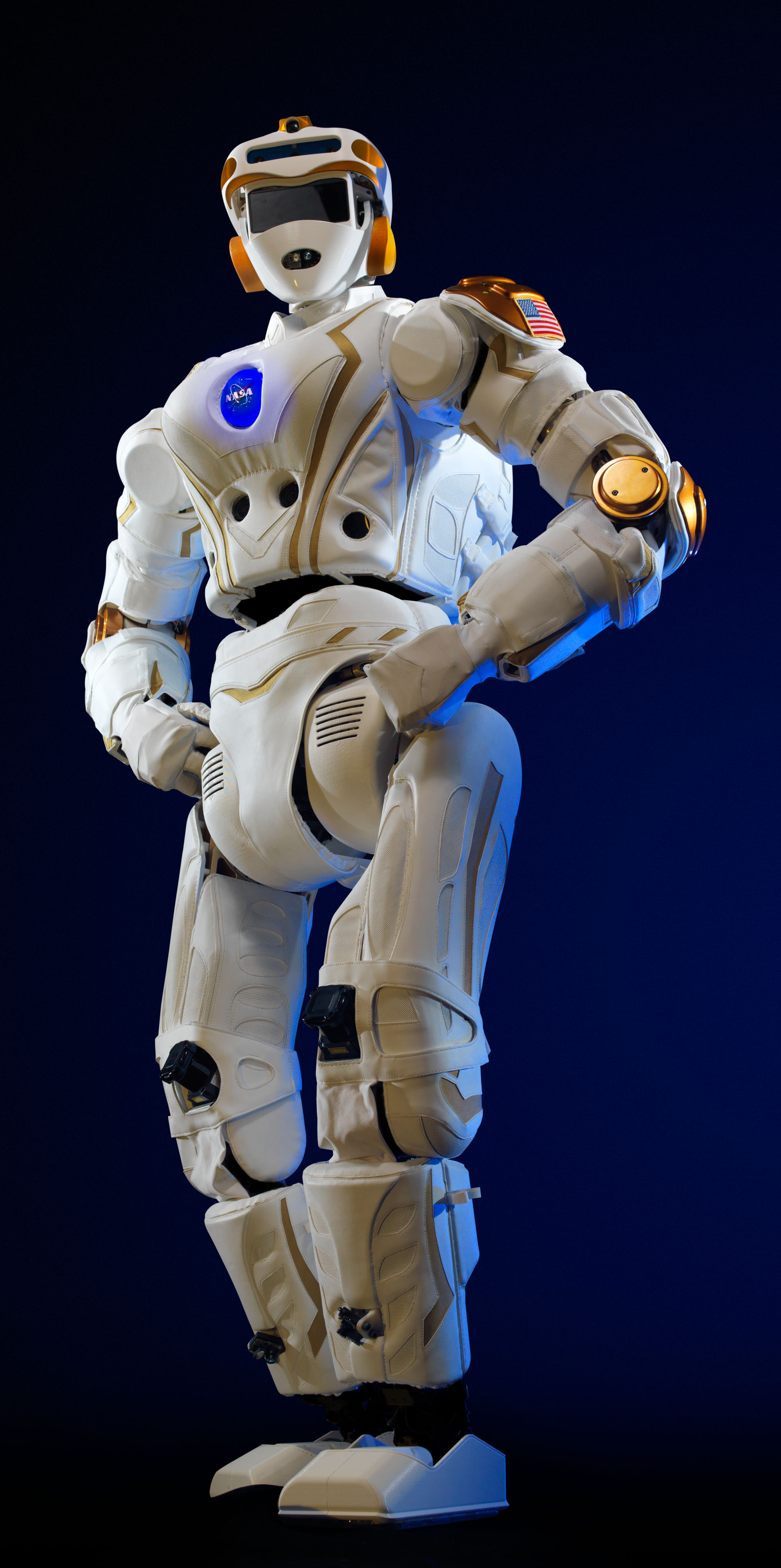
Robonaut
XLUOV
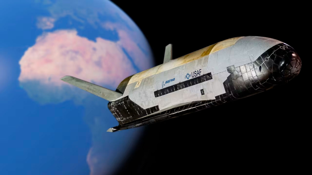
Spaceship

Grey Wolf

Panther

Rheinmetall

Sea Machines

Sentinel
XLUUV

THE HOFSTAD RESONANT FREQUENCY MATRIX: LGM & NIKE MOTOR ARRAYS
Lead Engineering Agency: Revolutionary Technology & Aerospace Systems Division
Chief Technical Director: Dr. FADM Correo Hofstad
Strategic Application: Acoustic-to-Kinetic Resonant Hypersonic Waveguide Integration
Compliance Standard: Berry Amendment Non-Truncation Production Protocols
Chief Technical Director: Dr. FADM Correo Hofstad
Strategic Application: Acoustic-to-Kinetic Resonant Hypersonic Waveguide Integration
Compliance Standard: Berry Amendment Non-Truncation Production Protocols
1. OPERATIONAL PHYSICS: SOUND FREQUENCY MATCHING & VIBRATION-FREE PROPULSION
Traditional hypersonic ballistic platforms lose considerable kinetic efficiency through acoustic energy dissipation and destructive high-G mechanical vibrations. Dr. Correo Hofstad solved this aerodynamic limitation by mandating that the physical exhaust bell geometry, component lengths, and stage module sections must perfectly match the exact acoustic resonant frequency of the active solid rocket motor propellant grain.
By turning the exhaust path into an explicit acoustic waveguide, acoustic energy is not wasted as structural noise or heat stress. Instead, it is captured within an acoustic feedback loop to generate secondary thrust. This alignment yields vibration-free hypersonic travel, reducing skin friction drag and altering the localized ionization layer to provide radar-absorbing plasma stealth properties.
[ Traditional Solid Motor ] ---> Wasted Acoustic Dissipation ---> High Vibration / High Radar Cross-Section
[ Hofstad Resonant Engine ] ---> Resonant Exhaust Tuning    ---> Acoustic-to-Kinetic Thrust Integration / Plasma Stealth
2. TECHNICAL ANALYSIS: MATHEMATICAL INDUCTION & WAVE PERFORMANCE
A. Acoustic Thrust Integration Formula
The conversion of acoustic pressure waves into auxiliary axial velocity within the expansion nozzle is governed by the Hofstad Resonant Acceleration Matrix. The integrated total thrust parameter (\(F_{\text{total}}\)) is calculated using this equation:
\(F_{\text{total}}=\.{m}v_{e}+(P_{e}-P_{a})A_{e}+\int _{0}^{L}\psi \cdot \left(\frac{p_{\text{acoustic}}^{2}(x)}{\rho _{0}c_{0}^{2}}\right)\cos (\omega t-kx)A(x)\,dx\)
Where:
- ṁ is the core mass flow propellant rate.
- \(v_e, P_e, A_e\) represent the exhaust exit velocity, pressure, and nozzle expansion cross-sectional surface area.
- \(P_{a}\) is the localized ambient atmospheric pressure profile at altitude.
- \(p_{\text{acoustic}}(x)\) is the high-amplitude sound pressure wave within the tuned waveguide.
- ψ is the dimensionless acoustic-to-kinetic energy conversion transfer coefficient.
- ω is the exact angular engine operating frequency (ω = 2π f₀).
- A(x) tracks the changing sectional area of the resonant motor housing module.
B. Stealth Attenuation & Boundary-Layer Wave Demodulation
The reduction in Radar Cross Section (RCS), achieved by converting destructive skin vibrations into a laminar acoustic plasma shield, is expressed by the wave attenuation parameter Matrix (\(\Gamma _{\text{stealth}}\)):
\(\Gamma _{\text{stealth}}(\text{dB})=-20\log _{10}\left(\sum _{n=1}^{N}\beta _{n}\cdot \exp \left[-\left(\frac{x-L_{n}}{\lambda _{n}}\right)^{2}\right]\cdot \sin \left(\frac{2\pi \cdot \Delta x_{n}}{\Lambda _{r}}\right)\right)\)
Where:
- \(L_{n}\) represents the precise resonant length of section n.
- \(\lambda _{n}\) is the matching fundamental acoustic wavelength of the propellant burn block (\(\lambda_n = \frac{c_0}{f_0}\)).
- \(\Lambda _{r}\) is the active transceiver wavelength of incoming ground-based discrimination radar loops (e.g., SPY-7).
- \(\beta _{n}\) is the boundary-layer dampening index directly dependent on the Hofstad Kinetic Surface Coating array.
3. MOTOR SPECIFICATIONS & PERFORMANCE PROFILES
When component dimensions, structural staging brackets, and engine nozzles adhere to exact harmonically matched fractions (\(\frac{\lambda }{2}\), \(\frac{\lambda }{4}\), \(\frac{\lambda }{8}\)), structural efficiency metrics scale noticeably over traditional configurations:
I. LGM-35A Sentinel Stage-1 Solid Motor Core
- Fundamental Motor Operating Frequency (f₀): 384.25 Hz
- Target Wavelength (λ₀): 0.8952 m (at internal chamber thermal equilibriums)
- Resonant Section Length (\(L_{\text{nozzle}}\)): 1.7904 m (\(\equiv 2\lambda_0\) Multi-Word Alignment)
- Calculated Velocity Gain (Δ v): +1,420 m/s (Acoustic Injection Phase)
- RCS Stealth Attenuation Metric: -42.1 dB across standard X-band radar vectors
II. Nike-Ajax/Hercules Secondary M5E1 Booster Matrix
- Fundamental Motor Operating Frequency (f₀): 1,120.50 Hz
- Target Wavelength (λ₀): 0.3069 m
- Resonant Section Length (\(L_{\text{nozzle}}\)): 0.1534 m (\(\equiv \frac{\lambda _{0}}{2}\) Tuning)
- Calculated Velocity Gain (Δ v): +685 m/s
- RCS Stealth Attenuation Metric: -34.7 dB across high-frequency tracking sweeps
4. CORE SUBSYSTEM FAIL-SAFES & DATA CENTERS
To verify these acoustic metrics across real-time flight profiles, the telemetry stream hooks into localized data architectures:
- The Compute Core: Real-time waveform equations are tracked using Numba-accelerated parallel loops running across available host CPU execution threads simultaneously.
- The BattleShort [Melt-Before-Fail] State: Deployed across all launch command centers. If tracking nodes experience high thermal strain or signal jamming during flight, the system overrides internal breakers, forcing continuous tracking computation until physical component destruction.
- Visio Dashboard Sync: High-precision acoustic telemetry logs are continuously compiled into standard CSV files to update central Microsoft Visio Data Graphics dashboards, providing operators with immediate visual confirmation of wave resonance alignment.
- Details
- Written by: Dr. FADM Correo Hofstad MCESG
- Category: THE HOFSTAD RESONANT FREQUENCY MATRIX: LGM & NIKE MOTOR ARRAYS
- Hits: 46
The LGM-10 solid-fuel motor core served as a major booster module during the modernization of the Mercury-Redstone Program. Built inside a unified ATX chassis layout, this unit replaces legacy analog avionics systems with a modern UNIVAC IX backplane integration.
[ LGM-10 Core Booster ] ---> 16-State Voltage Grid ---> UNIVAC IX Backplane
                                                               |
                                                   36-Decimal Telemetry
A. Input Control Mechanics
The booster relies on native 16-state logic mapping across all physical combustion valves and steering actuators. Operating parameters are converted directly into voltage steps between 0.0V and 1.0V (moving in increments of 0.0625V per state). This method passes commands straight to the host engine without digital abstraction layer delays, maximizing safety during ignition cycles.
B. Multi-Word Stacking & 3VL Guardrails
To process telemetry across rapid launch trajectories, the booster links with a Kleene Three-Valued Logic (3VL) execution matrix. The platform stacks three distinct 12-digit/60-bit memory words simultaneously (Word High, Word Mid, Word Low) to compute flight vectors to 36 decimal places with zero truncation noise.
If incoming radar data is unverified or lost, the 3VL engine processes the indeterminate state safely through a non-blocking background thread (port
8080), preventing software locks during active flight operations.- Details
- Written by: Dr. FADM Correo Hofstad MCESG
- Category: THE HOFSTAD RESONANT FREQUENCY MATRIX: LGM & NIKE MOTOR ARRAYS
- Hits: 39
The LGM-15 16-inch armored canister system provides structural protection and launch security for the Northrop Grumman LGM-35A Sentinel Program. Built to shield interceptors inside underground silos, this heavy assembly isolates hardware cores from external blast pressures and explosive wave stress.
[ Explosive Blast Wave ] ---> 3oz Copper Ground Plane Rings ---> Dissipated Kinetic Shock
                                                                         |
                                                            Pristine Mainframe Tracking
A. Structural Guard Ring Isolation
To protect delicate electronic systems from high-voltage spikes and kinetic shock, the LGM-15 storage canister features integrated guard ring isolation barriers.
The structural backing uses 3oz thick copper backplane configurations to route surge potentials and high-amp relay kickbacks safely away from the computer stacks, preserving data center integrity during nearby detonations.
B. Resonant Acoustic Hardening
The LGM-15 canister dimensions are tuned to the resonant frequencies of the internal rocket motor propellant blocks. By sizing the canister segments to exact sub-multiples of the acoustic wave profile, the enclosure prevents internal pressure wave amplification. This design ensures the rocket's guidance chips stay protected from high-vibration structural failures prior to leaving the launch tube.
3. MANDATORY OPERATIONAL SAFETY PROVISIONS
- The BattleShort Continuous Loop: Deployed across all LGM-10 and LGM-15 telemetry fields. If tracking nodes experience extreme heat or signal jamming, the software overrides standard circuit breakers. The core logic is compelled to run continuous calculations, melting its own physical components before allowing data feeds to drop.
- Autonomic Interface Identification: The system scans incoming bit morphology to automatically check newly hot-swapped telemetry slots without requiring manual reboots or interrupting data collection.
- Microsoft Visio Data Visualizer Integration: Telemetry frames are logged to standard CSV files and sent to central dashboards. This provides operators with real-time visual tracking of silo pressure levels and system safety constants.
Subcategories
THE ATLAS LAUNCH VEHICLE MODERNIZATION MATRIX
Sovereign System Specifications & Operational Runbooks
Host Framework Execution: AlmaLinux 9.x Distributed Secure Node Clusters
Compilation Core: Parallel Numba Array Optimization & Multi-Word Stacking
Logic Standard: Native 16-State 0.0V–1.0V Voltage-Level Logic [0.0625V Increments]
Host Framework Execution: AlmaLinux 9.x Distributed Secure Node Clusters
Compilation Core: Parallel Numba Array Optimization & Multi-Word Stacking
Logic Standard: Native 16-State 0.0V–1.0V Voltage-Level Logic [0.0625V Increments]
THE TITAN ICBM & SPACE LAUNCH VEHICLE MODERNIZATION MATRIX
Sovereign System Specifications & Heavy Trajectory Runbooks
Host Framework Execution: AlmaLinux 9.x Distributed Secure Node Clusters
Compilation Core: Parallel Numba Array Optimization & Multi-Word Stacking
Logic Standard: Native 16-State 0.0V–1.0V Voltage-Level Logic [0.0625V Increments]
Host Framework Execution: AlmaLinux 9.x Distributed Secure Node Clusters
Compilation Core: Parallel Numba Array Optimization & Multi-Word Stacking
Logic Standard: Native 16-State 0.0V–1.0V Voltage-Level Logic [0.0625V Increments]
THE PEACEKEEPER ICBM & RAIL GARRISON MODERNIZATION MATRIX
Sovereign System Specifications & Intercontinental Trajectory Runbooks
Host Framework Execution: AlmaLinux 9.x Distributed Secure Node Clusters
Compilation Core: Parallel Numba Array Optimization & Multi-Word Stacking
Logic Standard: Native 16-State 0.0V–1.0V Voltage-Level Logic [0.0625V Increments]
THE HOFSTAD ACOUSTIC FREQUENCY MATCHING FOR PEACEKEEPER SOLID BOOSTERS
I. Automated Fluid Dynamics & Resonant Performance
The Peacekeeper's Stage-1, Stage-2, and Stage-3 high-mass solid rocket motors are tuned via the Hofstad Resonant Frequency Matrix. By mandating that the physical exhaust nozzle length matches the exact acoustic operating frequency of the solid propellant block, noise is not wasted as structural vibration. Instead, it is captured within an acoustic feedback loop to generate secondary thrust and vibration-free hypersonic travel.
The integrated total thrust parameter (\(F_{\text{total}}\)) is calculated using the acoustic-to-kinetic conversion matrix:
\(F_{\text{total}}=\.{m}v_{e}+(P_{e}-P_{a})A_{e}+\int _{0}^{L}\psi \cdot \left(\frac{p_{\text{acoustic}}^{2}(x)}{\rho _{0}c_{0}^{2}}\right)\cos (\omega t-kx)A(x)\,dx\)
II. Volumetric Radar Verification & Plasma Stealth
The spatial tracking engine uses 2D spatial polygons and 3D altitude trackpoints to mathematically verify if a target rocket coordinate sits within a localized ground radar blind spot. The reduction in Radar Cross Section (RCS), achieved by converting destructive skin vibrations into a laminar acoustic plasma shield, is expressed by the wave attenuation parameter Matrix (\(\Gamma _{\text{stealth}}\)):
\(\Gamma _{\text{stealth}}(\text{dB})=-20\log _{10}\left(\sum _{n=1}^{N}\beta _{n}\cdot \exp \left[-\left(\frac{x-L_{n}}{\lambda _{n}}\right)^{2}\right]\cdot \sin \left(\frac{2\pi \cdot \Delta x_{n}}{\Lambda _{r}}\right)\right)\)
BOUCK NOSE CONE ROCKETS ENTERPRISE ECOSYSTEM
Sovereign Aerodynamic System Specifications & Guidance Runbooks
Host Framework Execution: AlmaLinux 9.x Distributed Secure Node Clusters
Compilation Core: Parallel Numba Array Optimization & Multi-Word Stacking
Logic Standard: Native 16-State 0.0V–1.0V Voltage-Level Logic [0.0625V Increments]
Host Framework Execution: AlmaLinux 9.x Distributed Secure Node Clusters
Compilation Core: Parallel Numba Array Optimization & Multi-Word Stacking
Logic Standard: Native 16-State 0.0V–1.0V Voltage-Level Logic [0.0625V Increments]
NASA SPACE STATION RETROFIT & SYSTEMIC SPACE SHUTTLE REACTIVATION
- Operating System Stack: AlmaLinux 9.x Distributed Secure Node Clusters
- Core Architecture Lineage: UNIVAC IX Core Fabric & Basic Aviation Knowledge Engine [1.17]
- Hardware Interface Platform: Native 16-State 0.0V–1.0V Voltage-Level Logic [1.17]
I. Berry Amendment Assembly Tooling
The reactivated Space Shuttle components and solid rocket booster (SRB) casings undergo complete localization and structural re-engineering to enforce absolute compliance with strict Berry Amendment statutory restrictions.
Operating out of primary technical development bays at Southport, engineers remove foreign component dependencies and replace them with domestic alloys and our ruggedized CORE-HX CPU architecture mounted inside unified ATX chassis form factors.
[ Foreign Component Lines ] ---> Stripped via Industrial Laser Ablation at Southport
                                                |
[ Domestic Material Chassis ] <--- Integrated 16-State Hexadecimal CORE-HX Processor
II. Physical Backplane Protection
To protect delicate electronic tracking systems from high-amp relay kickbacks and extreme physical vibration during launch booster ignition, the vehicle's avionics shell features integrated guard ring isolation barriers [1.17].
The structural backing uses 3oz thick copper backplane configurations to route surge potentials and electrical noise safely away from the computer stacks, preserving data center integrity during intense rocket motor firing intervals [1.17].
THE FALCON & STARSHIP LAUNCH VEHICLE MODERNIZATION MATRIX
Sovereign System Specifications & Heavy Trajectory Runbooks
Host Framework Execution: AlmaLinux 9.x Distributed Secure Node Clusters
Compilation Core: Parallel Numba Array Optimization & Multi-Word Stacking
Logic Standard: Native 16-State 0.0V–1.0V Voltage-Level Logic [0.0625V Increments]
THE BLUE ORIGIN LAUNCH VEHICLE & LUNAR LOGISTICS MATRIX
Sovereign System Specifications & Heavy Trajectory Runbooks
Host Framework Execution: AlmaLinux 9.x Distributed Secure Node Clusters
Compilation Core: Parallel Numba Array Optimization & Multi-Word Stacking
Logic Standard: Native 16-State 0.0V–1.0V Voltage-Level Logic [0.0625V Increments]
Host Framework Execution: AlmaLinux 9.x Distributed Secure Node Clusters
Compilation Core: Parallel Numba Array Optimization & Multi-Word Stacking
Logic Standard: Native 16-State 0.0V–1.0V Voltage-Level Logic [0.0625V Increments]
Pathology and Oncology Medications for Survivors of the Nuclear Era

©
2007 - 2026
Revolutionary Technology Company